Designfax Links
Archives Buyer's Guide Contact Us Events Calendar Features Media Kit Reader Favorites Readers Service Reprints Subscriptions


Archives Buyer's Guide Contact Us Events Calendar Features Media Kit Reader Favorites Readers Service Reprints Subscriptions
Previous articles examined design considerations for injection-molded parts (August 2000), the physical and mechanical properties of plastics (November 2000), and thermal, electrical and chemical properties of plastics (February 2001).
Ticona Corporation, Summit, NJ
Injection molding is the most prevalent way to make plastic components because it is economical, efficient and accurate. In working with this method, product designers must account for both the mold and the part itself. The overall design task should take into account every aspect of process from molding machine to processing conditions to resin.
Figure 1
Schematic of Reciprocating Screw Ingection Molding Machine
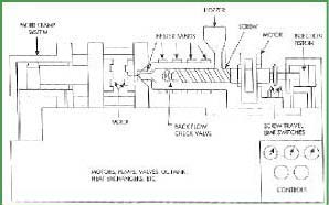
Injection molding is simple in concept -- plastic is melted, injected into a cavity and released when it has sufficiently hardened. Molding machines have an injection section that plasticizes and pushes the resin into the mold, and a clamping mechanism that opens and closes the mold. The process is usually worked with thermoplastics rather than thermosets, so only thermoplastics are considered here.

Most molding machines feed small, chopped plastic pellets from a hopper to a reciprocating screw that moves them through a heated barrel (the interaction between the rotating screw and the plastic also generates heat). The plastic melts and collects in front of the screw, which retracts until enough molten plastic is present to fill the mold. Shear generated by the flights of the screw mixes the melt so it is uniform.
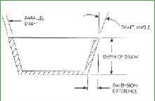
Figure 2
Illustration of Draft
The screw is then pushed forward hydraulically (a "shot"), forcing the melt through a nozzle into the mold where it is distributed by runners and passes through gates into part cavities. This occurs at pressures as high as to 30,000 psi. Water, or another fluid circulating through channels cut in the mold, removes heat so that the plastic cools and solidifies from the walls of the cavity inward. When parts are rigid enough, the mold is opened and they are removed. The next shot is melted in the barrel as parts cool in the mold. Cooling time generally controls mold cycle time and thus production rate.
Many variations exist on the basic injection molding process, for instance:
Each area of a molding machine involves important variables that affect a part. For instance, barrel temperature helps determine resin temperature and thus resin viscosity, while the pressure exerted on the melt controls injection pressure and speed. Other important machine conditions include screw speed, shot size, cavity pressure, clamp tonnage, gate size, mold temperature, venting and much more.
The properties of the plastic used, such as its flowability, heat transfer ability and cooling shrinkage, affect molding efficiency.
Flowability is a relative measure of how far a plastic will travel from a gate. It is often measured as spiral flow curves, which show the distance a plastic flows at a set pressure and temperature after being injected into the center of a spiral runner in a mold. Flowability depends on a resin's melt viscosity, shear resistivity and thermal conductivity and affects gate type, size and placement, the temperature and pressure used, and other factors.
Once a plastic fills a mold, the plastic should have enough heat transfer so parts do not warp because of differential cooling in the mold. A relatively uniform mold temperature also helps optimum part characteristics to develop as crystalline resins crystallize or amorphous ones anneal.
Mold cavities are sized to account for shrinkage as a thermoplastic solidifies from a shot, so finished part dimensions fall within tolerances. Shrinkage depends on the filler used and its orientation (fibrous fillers may cause more shrinkage in one direction than another). It also depends on part thickness and geometry (thin areas shrink less), gate and runner size, flow distance in the mold, and tool cooling and heating.
A well-designed mold allows for the broadest possible processing window so short-term changes in resin viscosity, hydraulic pressure and barrel temperature, and longer-term variations like screw and barrel wear, can occur over time with little loss in part quality.
Mold tool form and cost is often driven by the nature of the part. Complex parts with deep recesses and screw threads, for instance, may need expensive release mechanisms such as collapsing cores, side pulls, slides, multiple plates, automatic unscrewing devices or intricate parting lines. In addition to part complexity, mold designers must consider many other factors including:
The injection molding design task can be highly complex. Just the need to meet set tolerances ties in to all aspects of the molding process, including part size and shape, resin chemical structure, the fillers used, mold cavity layout, gating, mold cooling and the release mechanisms used. The machine itself is also important in how well it controls temperature, pressure and clamping forces, as well as screw and barrel wear.
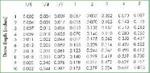
Table 1
Given this complexity, designers often use computer design tools, such as finite element analysis (FEA) and mold filling analysis (MFA), to reduce development time and cost. FEA determines strain, stress and deflection in a part by dividing the structure into small elements where these parameters can be well defined. While this method assumes a linear elastic material and is most often applied to structures under constant load, it can model nonlinear behaviors such as creep. Use of an anisotropic materials makes the calculations more complex.
MFA evaluates gate position and size to optimize resin flow. It also defines placement of weld lines, areas of excessive stress, and how wall and rib thickness affect flow. Other finite element design tools include mold cooling analysis for temperature distribution, and cycle time and shrinkage analysis for dimensional control and prediction of molded-in stresses and warpage.
In considering the overall design task for injection-molded parts, the high mold costs means that parts should have as many functions as possible. The ability to do this depends to a great degree on the plastic used. Designers should explore several candidate materials to find the best balance to meet the needed performance in the operating environment, cost constraints and other special requirements. And finally, designers should strive to use the least amount of plastic while satisfying structural, functional, appearance and moldability requirements. The next installment will look at methods for assembling plastic parts.
For more information:
Circle 445 -Ticona or connect directly to their website via the Online Reader Service Program at http://www.OneRS.net/105df-445
| CLICK HERE! | ||||
|---|---|---|---|---|
| Home Modern Applications News | Metlfax | Mfg Resources | QM | Designfax Tooling & Production |
| Designfax | ||||
6001 Cochran Rd., Suite 104 Solon, OH 44139 Phone: 440.248.1125 Fax: 440.248.0187
To request a media kit or back issues click here. (US & Canadian requests only) Please report problems with this site to the Designfax site manager.
Copyright © 2004 by Nelson Publishing, Inc.. All rights reserved. Reproduction Prohibited. View our terms of use and privacy policy.