In the design of plastics components, it is important to aim for uniform wall thickness. Different wall thickness in the same component causes differential shrinkage that, depending on component rigidity, can lead to serious warping and dimensional accuracy problems.
One way to obtain uniform wall thickness is to use cores in thick-walled areas. This explains why injection molded parts typically have open internal spaces. Eliminating thick wall areas prevents the risk of void formation and reduces internal stresses.
Voids and microporosity in the component severely reduce its mechanical properties by cross-sectional narrowing, high internal stresses and in some cases notch effects. It also minimizes the tendency to warp.
  |
| |
|
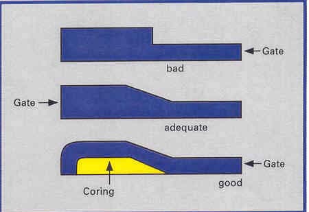
Figure 1. Use Cores To Create Uniform Wall Thickness
|
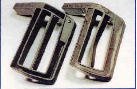
Figure 2. Thick to Thin Wall Transitions Can Lead to Warping
|
Not all designs can be satisfied with a uniform wall thickness. Wall thickness should not vary more than 10 – 25%. If greater variations are unavoidable, transitions should be gradual and the polymer should flow toward the thin sections, so that thick areas fill well and stress is minimized.
Material accumulation is another example of non-uniform wall thickness. It can occur, for example at the base of a rib, and has a tendency to form sink marks. This occurs when the areas with less material accumulation cool and solidify. During solidification, the material shrinks and pulls from the area of high material accumulation. This forms a dimple, or sink mark, which gives a lower quality part because of the surface imperfection. Avoiding material accumulation is especially important for ribbed components that require a high quality surface finish, such as hubcaps.
Areas of material accumulation can also lead to voids and microporosity. Again, this is caused when the surrounding areas with less material cool faster and pull in the still molten material from the areas with high material accumulation. Voids and microporosity in the component severely reduce its mechanical properties by cross-sectional narrowing, high
internal stresses and in some cases notch effects. It also creates the tendency to warp. The following figure shows guidelines for limiting material accumulation in a ribbed component design.
 |
|
Figure 3. Rib Design With Limited Material Accumulation |
Wall thickness design affects critical component function and costs, such as:
-
Component weight, which effects component cost through cycle time and material cost
-
Achievable flow lengths in the mold
-
Rigidity of the molded part
-
Tolerances
-
Component quality in terms of surface finish, warping, and voids
Walls should be as thin as possible, without sacrificing mechanical integrity, to minimize component cost. Features such as ribs and gussets can be used to increase the rigidity of thin walled areas (see following section).
Early in the design stage, it is important to evaluate if the proposed wall thickness can be achieved with the desired material and process. When evaluating designs for injection molding, the ratio of flow path to wall thickness has a critical influence on mold fill. If long flow paths are combined with low wall thickness, a polymer with relatively low melt viscosity must be used. Typical wall thickness for injection-molded parts is usually 0.030 inch to 0.190 inch. This is highly dependent on the material selection.
 |
 |
|
|
Figure 2. Thick to Thin Wall Transitions Can Lead to Warping
|
Use Ribs To Replace Thick Wall Sections Oftentimes, with metal component designs, wall thickness is increased to improve rigidity with limited affect on cost. This is true because the machining cost, which can be a major driver of the metal component cost, does not significantly change while the material cost remains constant.
For plastic designs that require high rigidity, the better approach is to use ribs or other cross-sectional features to increase the moment of inertia of the cross-section. Not only does this improve the quality of the part by minimizing the risk of voids and microporosity, it decreases material content and cycle time, thus lowering component cost.
Multiple, evenly spaced ribs usually distribute loads better than one large rib. The thickness of a rib at its base is usually half that of the adjacent wall, but can equal that of the wall if structural integrity matters more than appearance or if the resin has little shrinkage. Rib height is typically 2.5 to 3 times wall thickness.
| |
|
 |
 |
|
Figure 4. Rib Design Examples |
Figure 5. Rib Design To Minimize Material Accumulation
|
Though ribs are the most common methods to add strength, there are other features that can also add strength. These are gussets (small triangular ribs), corrugations, and crowning.
Figure 6. Features To Increase Component Rigidity
Radius! Radius! Radius!
Stresses that accumulate in sharp corners as a plastic shrinks after molding can cause failure under high load or impact. To avoid this, use generous radii on corners where ribs, bosses, sidewalls, and other features connect. Inside corner radii vary with stress. In stress-free areas, radii can be as small as 0.005 inch, while those where loads are high should have a radii of over 0.020 inch. The radius of the outside corner should equal that of the inside corner plus the wall thickness to ensures a constant cross-section.

Figure 7a. Stress Concentrations Form at Sharp Corners of Ribs Figure 7b. Stress Concentrations Are Reduced with Corner Radius

Avoid Flat Areas
Large flat areas are prone to warping. If the design requires flat areas, it is recommended to add ribs on the underside, if possible, to add rigidity. Other options to increase rigidity are gussets (small triangular ribs), corrugations, and crowning. When a flat area is required, different materials with less shrinkage could be evaluated to decrease the level of warping.
Avoid Undercuts
Undercuts add to component cost through the increased complexity and cost of the mold. Undercuts typically require a separate core and cam action to create the feature because the component cannot be stripped off the mold. When possible, eliminate the undercut or use a low cost mold design, such as that shown below.

Figure 8. Low Cost Snap-Fit Mold Design
Use Bosses For Points Of Attachments
Since the component is now designed with minimum wall thickness, additional material must be added to support fasteners such as screws. Bosses should be no thicker than the nominal wall and can be strengthened by gussets to counter lateral forces.

Figure 9. Recommended Boss Design
Provide Proper Draft For Easy Removal Of Molded Components
Parts should be designed so mold tools open and eject the part easily. This is most often done by tapering ribs, bosses, and other elements. Taper (or draft) should be at least 0.5 degree per side, although 1.5 to 3 degrees per side is more common. Draft also depends on mold surace finsih, and increases at least 1 degree per side for each 0.001 inch depth of texture. A 1 degree draft yields a 0.017 inch taper per inch of length.
If the draft design is not correct, rejection rate can increase as parts are damaged during withdrawal. It may also require the use of special processing steps, such as the use of parting spray or mold coatings. Deceases in product yield and the use of additional processing steps and materials will increase process costs.
Typical draft values are described in the following figure.

Locate Parting Lines, Gate, and Knock-Out Pins Appropriately
The location of parting lines, gates, and know-out pins greatly affects the tooling cost and the quality level of the component.
Parting lines are the lines on the component where the tool halves come together. Parting lines that cross a critical face may require a secondary operation to remove flash. Parting lines that cross a feature with tight tolerance may lead to decreased yield due to mold mismatch. Since parting lines will be noticeable as a bump on the surface of the part, they should not be located on a sliding surface. Similarly, parting lines should not be located on a sealing surface where a "bump" or mismatch should prevent the seal form making complete contact.
Gate location has a significant role in component quality. It affects the filling behavior, final part dimensions, shrinkage, warping, mechanical property level, and surface quality.

Weld lines are formed when two or more melt streams come together in the mold. This happens, for example, when melt has to flow around a core or if the component is gated in several areas. Weld lines are often visible as surface defects. Gates, like parting lines and knock-out pins, leave visible marks on the component surface. Thus, gating should be designed to prevent visual defects from forming in areas where surface quality is important.

Basic gating design principles are as follows:
-
Do not gate parts in highly stressed zones
-
Avoid or minimize weld lines
-
Avoid leaving weld lines in highly stressed areas
-
With reinforced plastic, gate locations determine part warping
-
Avoid air entrapment by providing adequate vents
Since most injection molded components have similar features (walls, ribs, radii, bosses), the design guidelines presented here can be used for most injection molded parts. The quality level required by the specific application, though, can vary and should override any of these general guidelines. Proper component design, along with proper mold design, can lead to a lower cost, higher quality component and minimize more expensive design changes later on in the development.
